Crane Runway Beam Design Software
The attached is from my drawing notes for crane loading (This is for Canadian Codes; EU may have something similar. Notes in square brackets are to be edited for the project. This is from a particular project. Format is a little wonky for proportional fonts.
Modify to suit.) I have similar notes for Jib Cranes, etc.: OVERHEAD CRANES (GENERAL) COMPLETE OVERHEAD CRANE ASSEMBLY AND INDIVIDUAL COMPONENTS OF CRANE ASSEMBLY TO BE CSA CERTIFIED OVERHEAD CRANE COMPONENTS SHALL BE DESIGNED FOR A CORROSIVE ENVIRONMENT. ALL WELDS SHALL PROVIDE A CONTINUOUS SEAL. ALL COMPONENTS SUBJECT TO CORROSION SHALL BE STAINLESS STEEL. HDG MATERIAL SHALL NOT BE USED. Hi guys, I have a bit of an unusual situation. So, in reality I'm designing some stairs in which the flights/landings cantilever off of columns in the central well of the structure.
All sections of the structural members will be hollow section (beams and columns) and the senior engineer doesn't want to use hollo-bolts or anything similar. His suggestion for the connection is illustrated in the picture attached. Minecraft New York City Map Download 1.6.4.
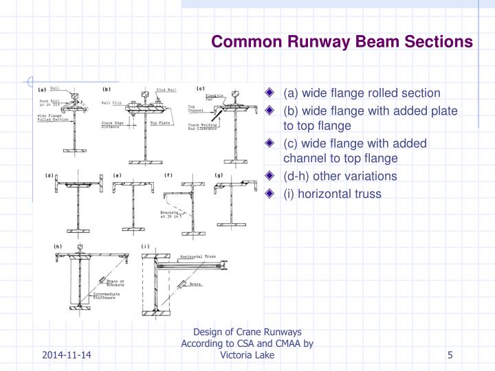
Their solution is best achieved using spreadsheet software, or by the use of the design capacity tables given in Woolcock et al. Conclusions Crane runway beams are usually compound monosymmetric beams, and so their design against the limit state of lateral buckling must make recourse to design rules for.

My concern is, this thin plate connection would need to resist bending plus torsion, would it be any effective in doing so? Or am I overthinking it? If you have any suggestions on how to design the connection and make sure it works as intended that would also be great!
Hello once again. I am designing a crane bridge girder with capacity 10T, span 12m and running on bottom flange (1st time) according to CMAA74.
It will be box section made from joining plates. I have made the calculations for the global and local stresses, as well as checked the combinations. But I have doubt, when shall we use the intermediate stiffeners (diaphragms). Section 3.5. Logitrace Serial Keygenreter. 4.1 tells the requirements when h/t>240/(tau)^0.5 and buckling stability requirements as per section 3.4.8 are not satisfied. I am not able to interpret the section 3.4.8; My interpretation for section 3.4.8 is as follows (please correct me) 'If ϑB>DFB, then no stiffeners (diaphragm) are required.' I have tried many combinations with many load cases(with comp and shear stress close to their allowable limits), but never found the requirement for stiffeners according to section 3.4.8.
Please do reply.